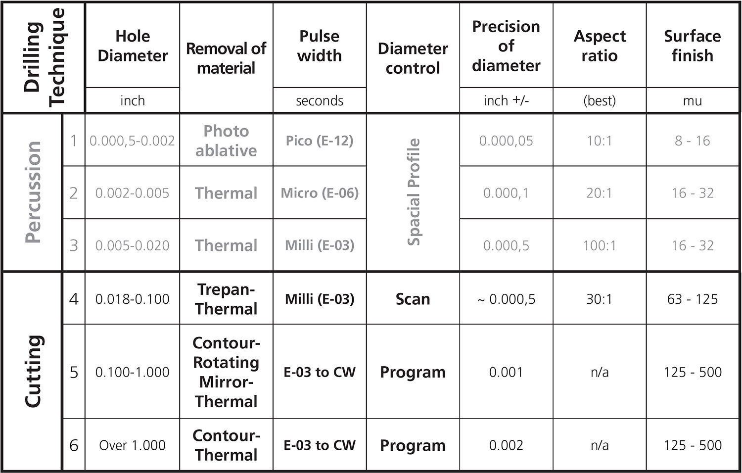
ypically, percussion laser drilling holes larger than approximately 0.020 in. diameter in metals by defocusing the laser beam is not typically practical. The demand for laser power is too high to produce the required power density. So, we cut a circular path with a focused beam to drill the holes. (For classification, see Figure 1.) Pulsed laser power is preferred for the following reasons:
- The high peak power densities achievable even from lasers with modest average power.
- Good coupling of the laser into the metal (surface effect).
- The precise control of the diameter of the hole.
- Good control of the total heat input (pulse width, overlap of pulses and duty cycle)
- The minimal heat-affected zone.
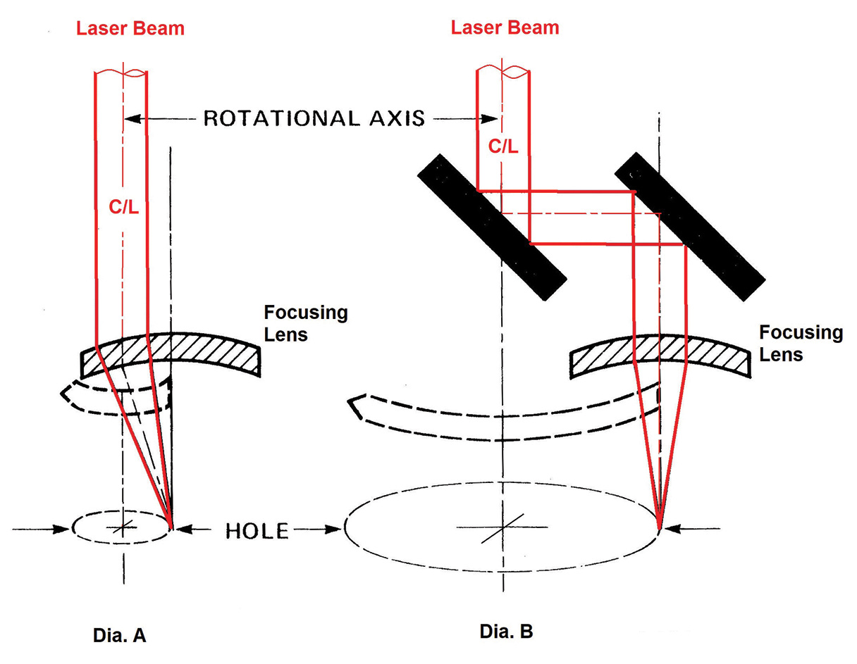
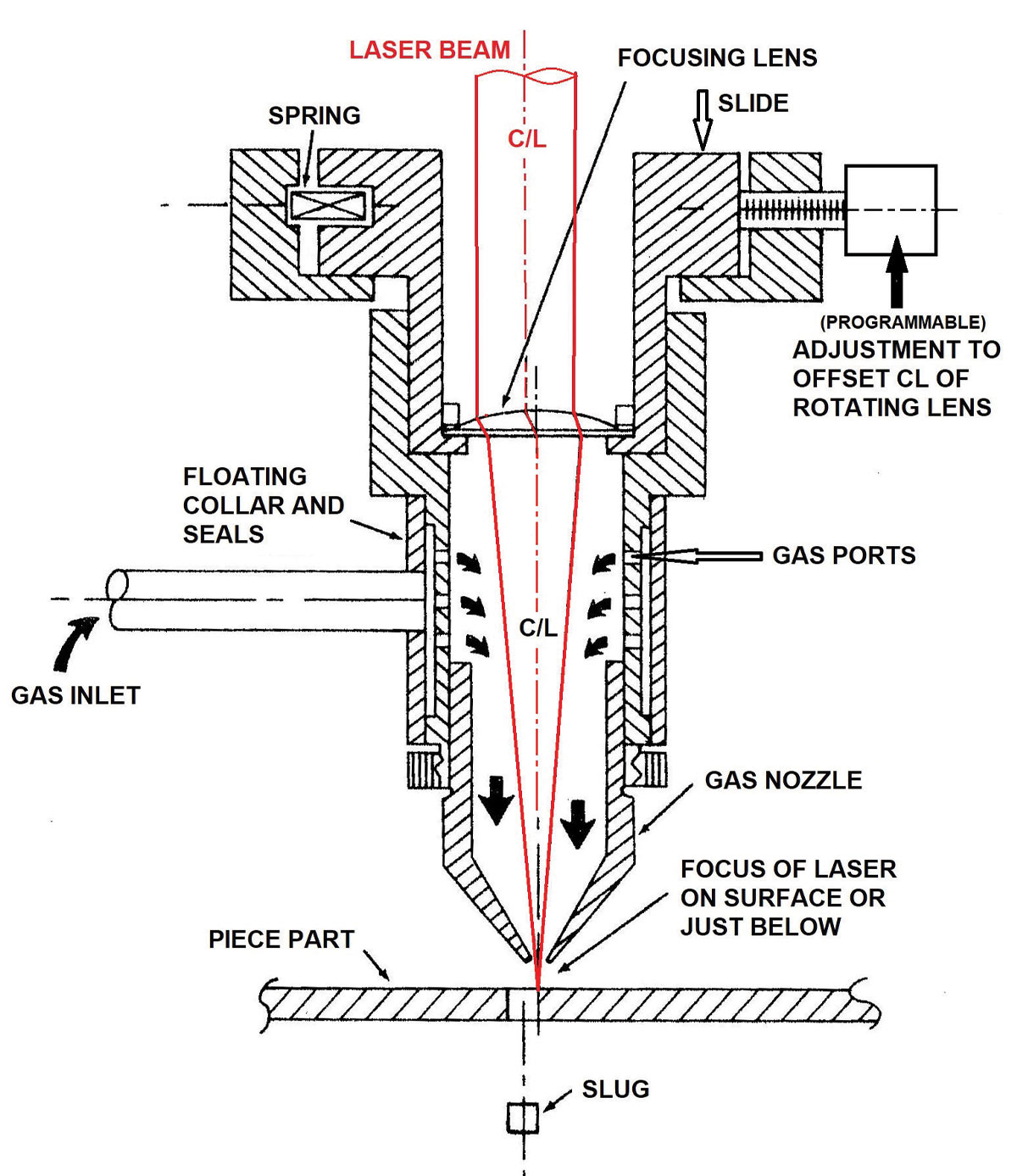
High-pressure gas assist as delivered by a coaxial nozzle is desirable, especially when performing thermal laser drilling (TLD). This requirement specifies the type of optical arrangement. (See Figures 2 and 3.)
In the diameter range of 0.020 in. and 0.100 in., we cut a circular path using trepanning optics (Figure 2, Diagram A). We focus the laser beam to produce the highest peak power density for efficient surface effect. The final focus lens is rotated around the centerline of the laser beam.
As we increase the distance between the centerline of the lens and the centerline of the laser beam, the diameter of the hole changes. The offset of the lens may be changed programmably. The “bulk effect” of the process is efficient since the material in the center of the hole (a “slug”) is not actually vaporized/melted by the laser.
The rotating mirror system covers the range of hole diameters from 0.10 in. to 1.0 in. (Figure 2, Diagram B). The minimum diameter of holes that may be drilled with this method is defined by the actual design of the beam delivery hardware. Everything stated for the trepanning optics is still valid, including the programmable offset of the final focusing mirror. The “bulk effect” of this process is efficient since the slug is not affected by the laser beam. Both of these drilling methods may be compared to conventional core drilling.
Laser drilled holes much larger than approximately 1.0 in. diameter are typically produced by programming a contoured path with the motion system. The smoothest surface finish in the kerf of the holes is realized at about 80 percent overlap of the holes generated by the focused laser beam. The preferred spatial profile of the laser beam is top hat, and power density of the focused beam must still be the correct value to vaporize the metal. The “lead-in” and “lead-out” may also be programmed.
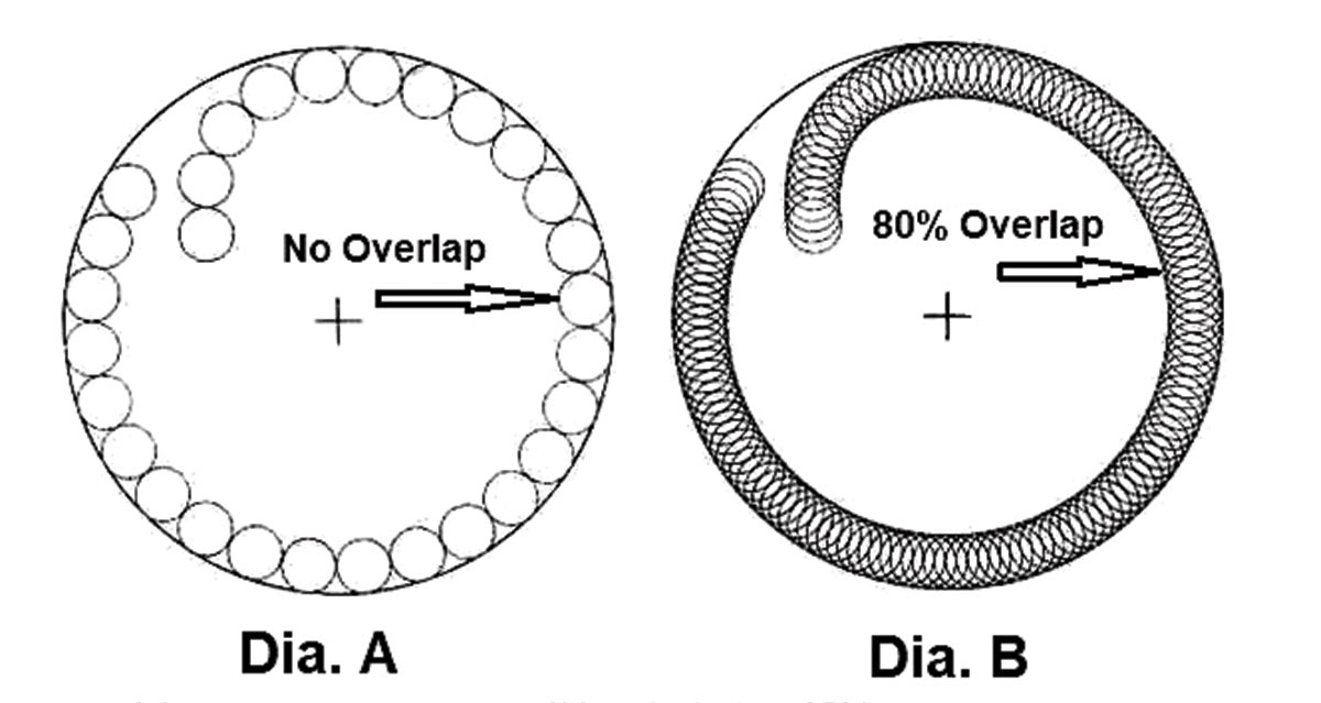
- Optimum ratio of focused spot diameter to diameter of desired hole = 0.1
- Optimum overlap of focused spot diameter = 0.8 (80%)
Let’s compute the production speed for drilling 0.100-in.-diameter holes in 0.030-in.-thick stainless steel. The hole may be produced by both trepanning and contouring.
Using the information published in FFJournal’s December 2019 Laser Expert column (Figure 4), one can use following settings:
- Focused beam diameter of 0.010 in. (10 percent of 0.10 in.). 80 percent overlap of pulses.
- Energy = 8.0 joules per pulse, pulse width = 0.002 seconds.
- Power density value of 5.09E+07 watts/in.^2. (Algorithm 04 in the “Laser Cutting and Drilling Technology Engineering Manual,” published by HDE Technologies Inc.)
- Peak Power = 4,000 watts
Choice of lasers (for about the same cost):
For an Nd:YAG pulsed laser, rated at 5,000 watts peak, 500 watts average, at the pulse rate of 60 PPS, the drilling time would be less than 2.36 seconds. This performance is beyond the capability of large Cartesian positioning systems.
For a QCW pulsed fiber laser, rated at 6,000 watts peak, 600 watts average, at the pulse rate of 75 PPS, the drilling time would be less than 1.88 seconds. This performance is also beyond the capability of a Cartesian positioning system.
